
Quick Links

The rapid development of the new energy vehicle industry has driven explosive growth across various industrial chains. Vehicle intelligence and autonomous driving have become the most critical competitive edge directions for new energy vehicles, bringing new challenges and opportunities for highly integrated central brains and domain controllers, especially in terms of the reliability, high power density, switch power supply EMC, high efficiency, and high cost-performance of DC-DC switching power supplies.
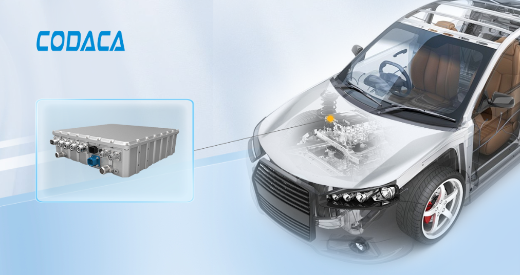
Qualcomm, as a supplier of intelligent cockpit domain controllers, holds a significant position with the SA8155 and SA8295. The conflicts between the transient current, stable operating current, standby power efficiency, cost, and switch-mode power supply (SMPS) EMC design of the central domain controller SOC primary power (power from battery input to primary conversion) become a major challenge for BUCK power supply design. How to resolve and balance these conflicts is the technical direction where the switch-mode power supply architecture, power chips, inductors, MOSFETs, and capacitors work together.
This article combines the design of the central domain controller's primary power supply for automotive applications with large dynamic switch-mode power supply current (100-300%), exploring the design of DC-DC switch-mode power supplies, including power supply solutions, inductor, and capacitor selection methods. It discusses and implements practical design while addressing challenges in volume, cost, efficiency, and performance.
This article takes Qualcomm's SA8295 domain controller as an example to explore and implement the practical design of the primary BUCK switch-mode power supply.
This series of articles includes three parts (to be continuously updated):
01- Decoding Qualcomm Automotive Domain Controller First-Stage Power Supply Design: Power Supply Design and Calculation (this chapter)
1- Design Objectives and Challenges
1.1 Transient Current Requirements for SA8295
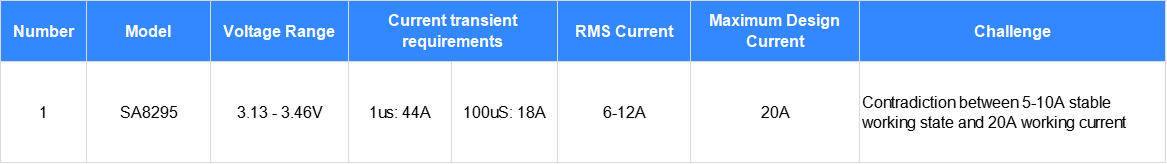
Table 1: SA8295 Power Design Requirements
1.2 SA8295 Standby Current Requirements
Qualcomm SOC 3.3V power supply standby power consumption within 4-7.5mA (including memory self-refresh power consumption), support standby wake-up.
Central Brain (Cabin Domain Controller) overall vehicle current budget 7-10mA (13.5V), 4G/5G module consumes 4-5mA alone, Qualcomm SA8295 current 13.5V 3mA (40mW) or less.
1.3 Three challenges
1.3.1 Challenge 1: Qualcomm Domain Controller SA8295 switching power supply current output
Large transient current, 3.3V, 18 amperes (0.1ms), 0.1ms is already a long period steady state output for DC-DC switching power supply, requiring the buck power supply to be designed for stable 18 ampere output.
1.3.2 Challenge 2: High-Quality Domain Controller SA8295 Switching Power Supply Dynamic
The steady-state working current of the SA8295 domain controller is 5-9 amperes, which will cause a stable working current difference of over 300% in the switching power supply inductance (the inductance is inversely proportional to the rated current) in terms of volume, cost, and frequency, resulting in significant conflicts.
1.3.3 Challenge 3: High-Quality Domain Controller SA8295 Switching Power Supply Micro-Power Efficiency
Standby power consumption, with an efficiency 70% at 13.5V 3mA, poses a huge challenge to the power supply controller architecture and inductor selection design.
This design is based on the challenge of the maximum SA8295 primary buck power supply design, exploring the core difficulties of switching power supplies and DC-DC technology solutions.
2- Solution Selection Comparison
2.1 Qualcomm SA8295 Domain Control Power Supply Technical Requirements
As shown in table 2:
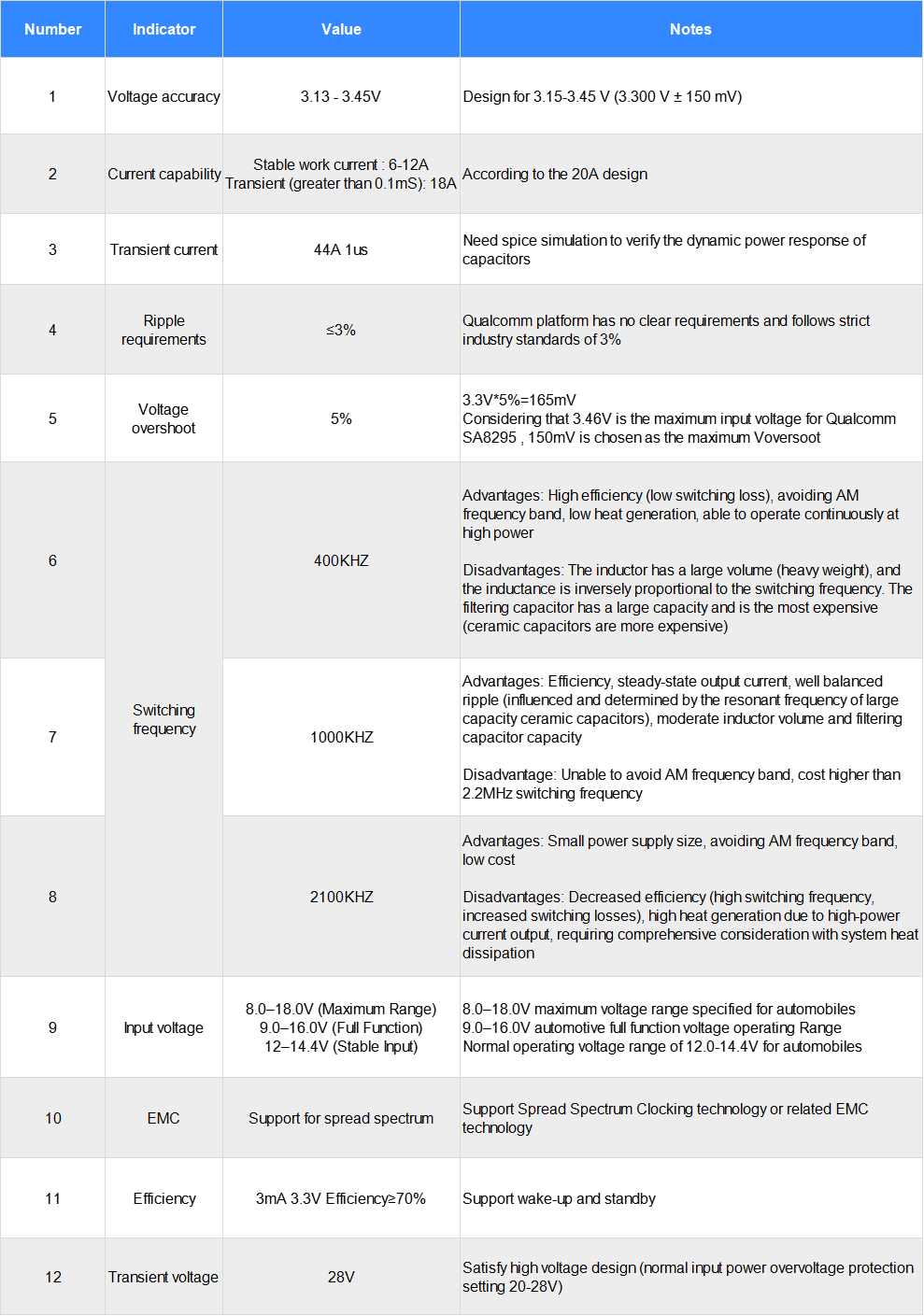
Table 2: Qualcomm SA8295 Power Design Technical Specification Requirements
2.2 Design Scheme and Technical Documents
MPQ2918, MPQ2930, LM25141-Q1, MAX20098, LTC7803, LM25149-Q1, etc., can all meet the design requirements. This design selects LM25149-Q1 as the central brain domain controller primary power supply design scheme for this project.
2.2.1 Official LM25149-Q1 address:
https://www.ti.com.cn/product/cn/LM25149-Q1?keyMatch=LM25149-Q1
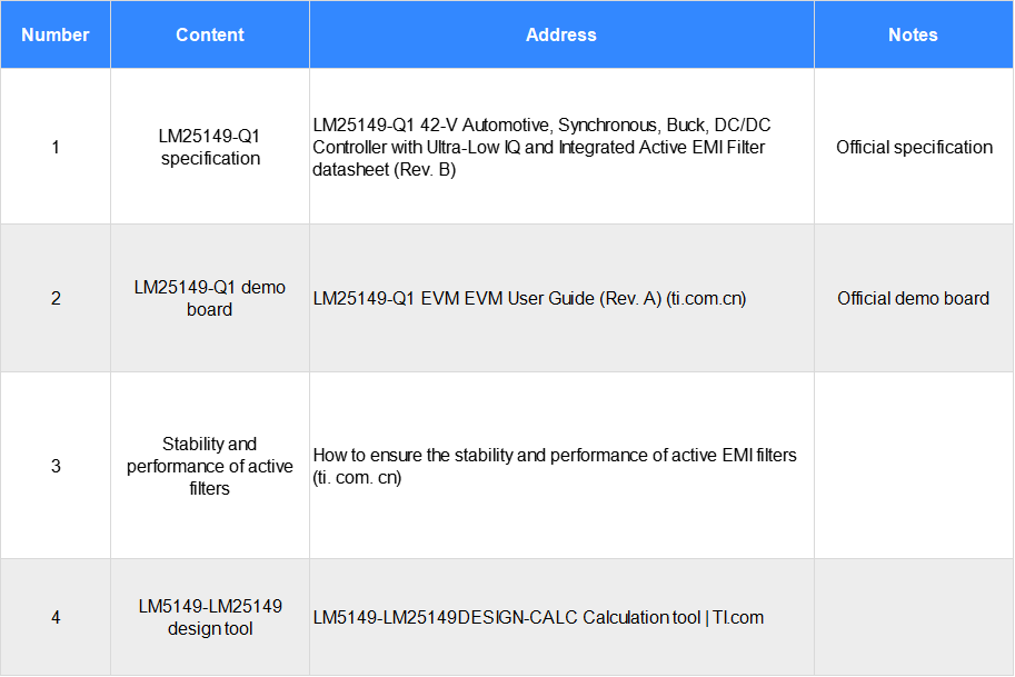
Table 3: LM25149-Q1 Design Reference Materials
2.2.2 LM25149-Q1 Specification Sheet:
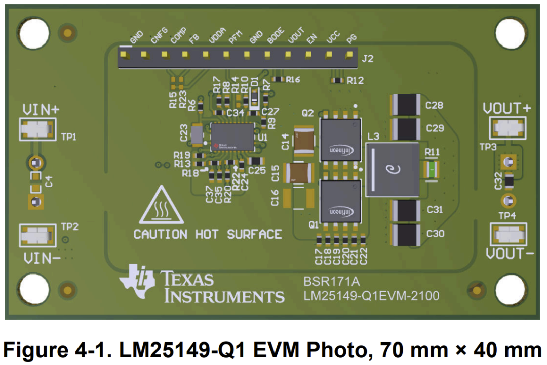
2.2.3 LM25149-Q1 Development Board:
LM25149-Q1 EVM User Guide (Rev. A) (ti.com.cn)
2.2.4 Active Filter Stability and Performance:
How to Ensure Stability and Performance of Active EMI Filters (ti.com.cn)
2.2.5 LM5149-LM25149 Design Tools:
LM5149-LM25149DESIGN-CALC Calculation tool | TI.com
3- Synchronous BUCK Power Supply Design and Calculation
3.1 Main specifications and design parameters of LM25149
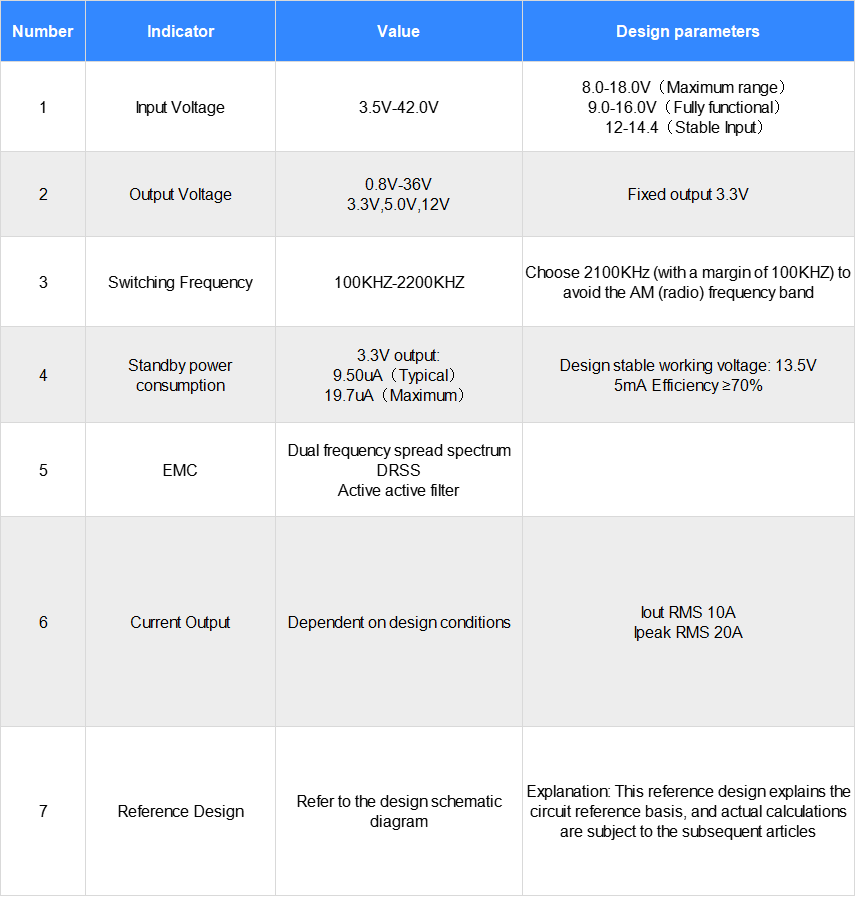
Table 4: Qualcomm SA8295 Power Design Technical Specifications Requirements
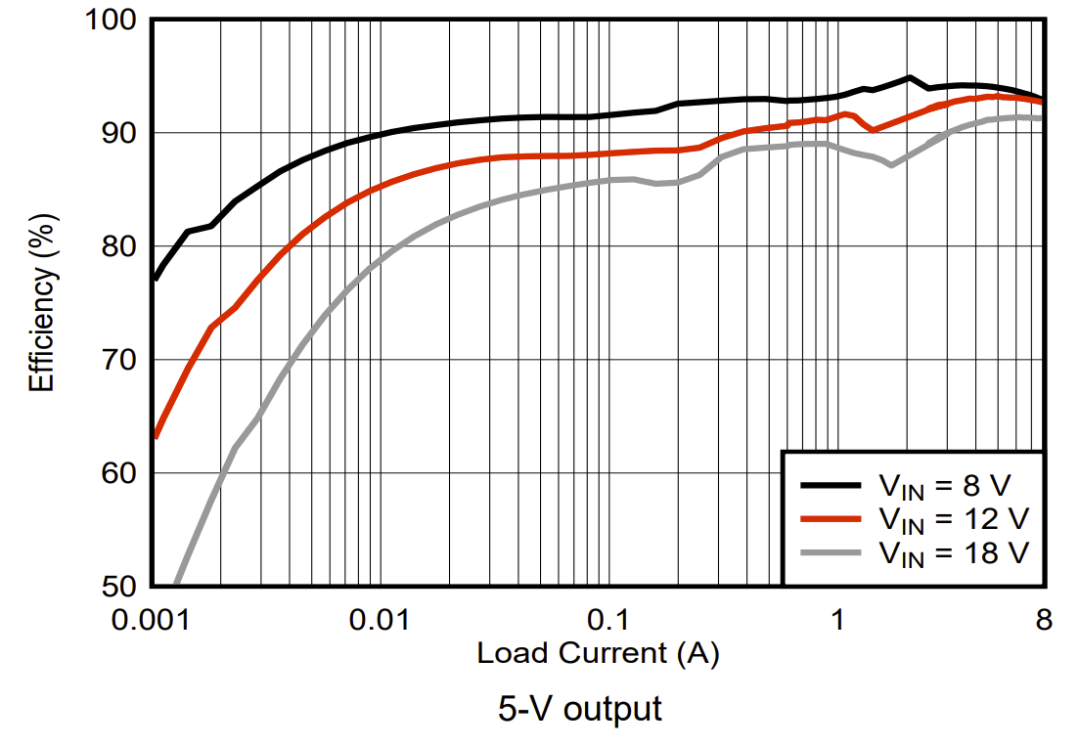
Efficiency
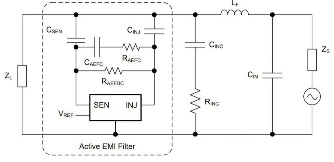
Active EMI Filters
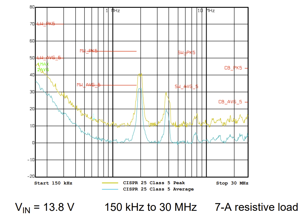
EMI Testing
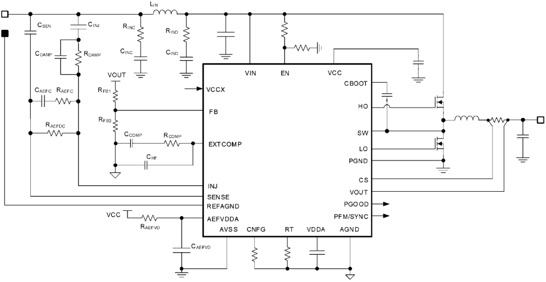
Reference Design Schematic
Reference Design Solution Evaluation Board
3.2 LM25149 Synchronous BUCK Inductor Selection Calculation
3.2.1 Synchronous BUCK switching power supply calculation formula:
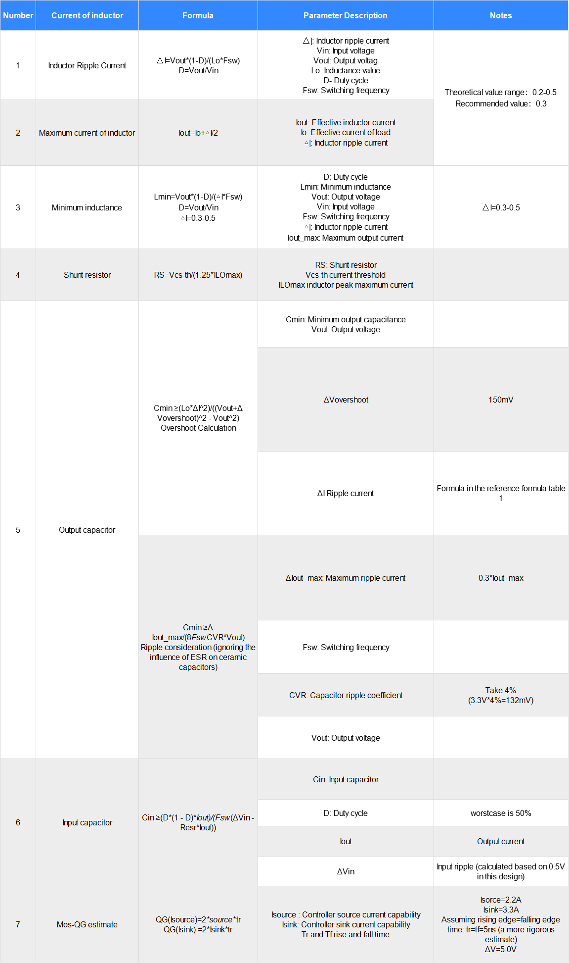
Table 5: Synchronous BUCK Power Supply Design Calculation Formulas
3.3 Minimum Inductor Calculation
(Calculation formula, see Table 5.)
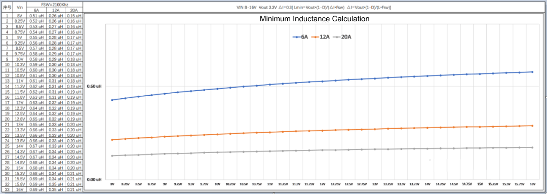
Table 6: Minimum inductance calculation curve chart (∆I=0.3)
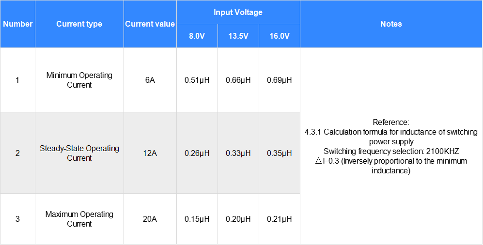
Table 7: Minimum inductance calculation
3.3.1 Summary of inductance calculation data:
① If the design covers the range of 6-20A (AI=0.3 calculation), with a 16V input and 6A output, the inductance shouldc be ≥0.69μH.
② Theoretical calculation of switching power supply inductance Lmin: ≥ 0.69μH (theoretical);
③ Considering the actual design selection and inductor tolerance ±20%, choose 0.82μH and 1.0μH as the optimal design (increasing inductance value increases inductor size, cost, and reduces SRF).
3.4 Inductor Current Calculations
(Formula: refer to tables 5, items 1 and 2)
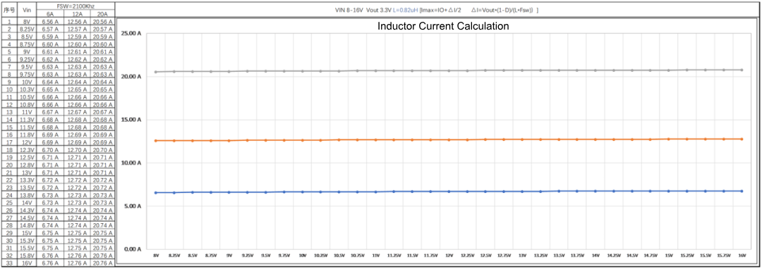
Table 8: 0.82μH Inductor Current Calculation
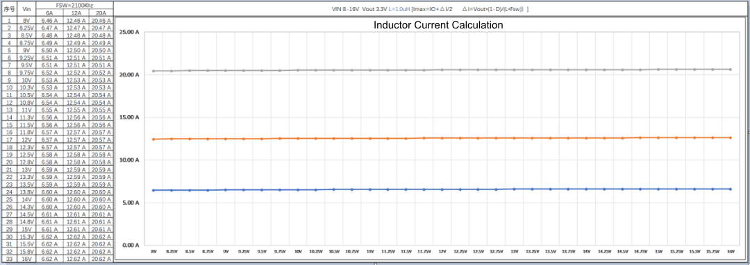
Table 9: 1.0μH Inductor Current Calculation
3.4.1 Theoretical calculation inductance saturation current ≥ 20.76A, rounded to 21A:
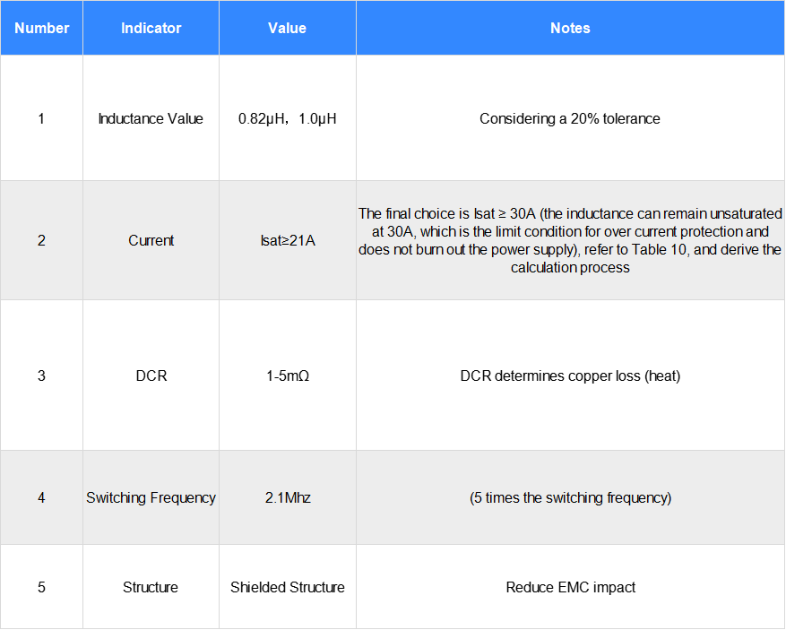
Table 10: Inductor specifications
4- Inductor selection for Switching power supply
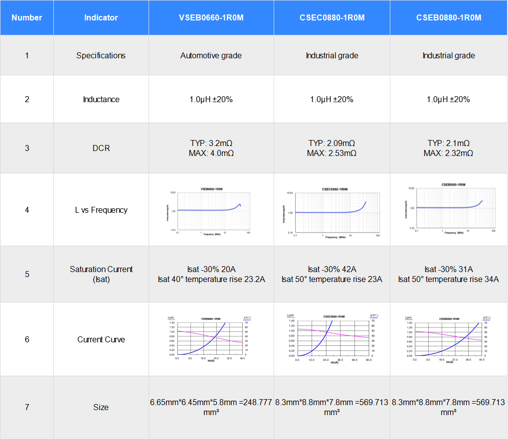
Table 11: Inductor Selection
4.1 Calculation of Current Sampling Resistor Switching Power Supply for LM25149
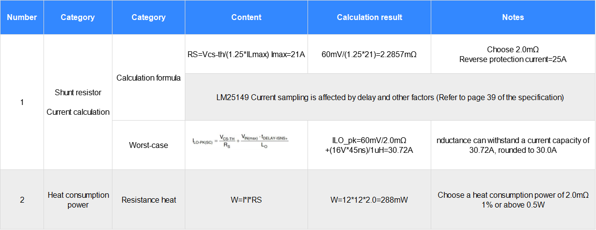
Table 12: Theoretical Calculation of Current Sampling Resistor
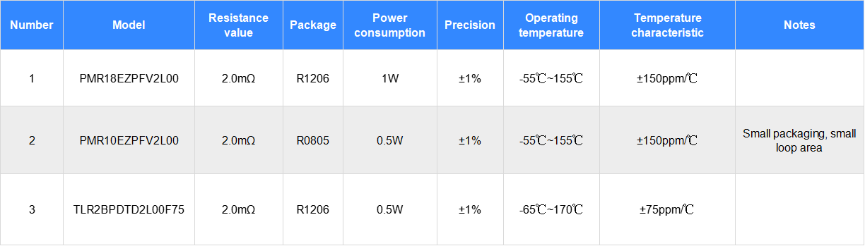
Table 13: Current Sampling Resistor Selection
4.2 Calculation of Output Capacitor for Synchronous BUCK Switching Power Supply
(Output Capacitor Calculation: Refer to Equation in Table 5)
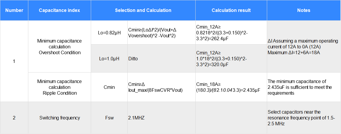
Table 14: Calculation of Output Capacitor for Synchronous BUCK Switching Power Supply
For synchronous buck switch-mode power supply designs, there exists a trade-off between the performance, size, and cost of input and output filter capacitors. Capacitor specification testing is conducted under specific conditions, and variations in instrumentation during testing may yield discrepancies of 10–50% for identical specifications. The ultimate design performance requires scientific validation and testing through the debugging process (there is no single optimal solution; only the selection of a scheme suitable for the specific application).
Switch capacitors need to meet: Capacity ≥ 320uF (Overshoot requirement), ceramic capacitor capacity greater than 2.435uF (not a core condition, meeting the requirement is sufficient).
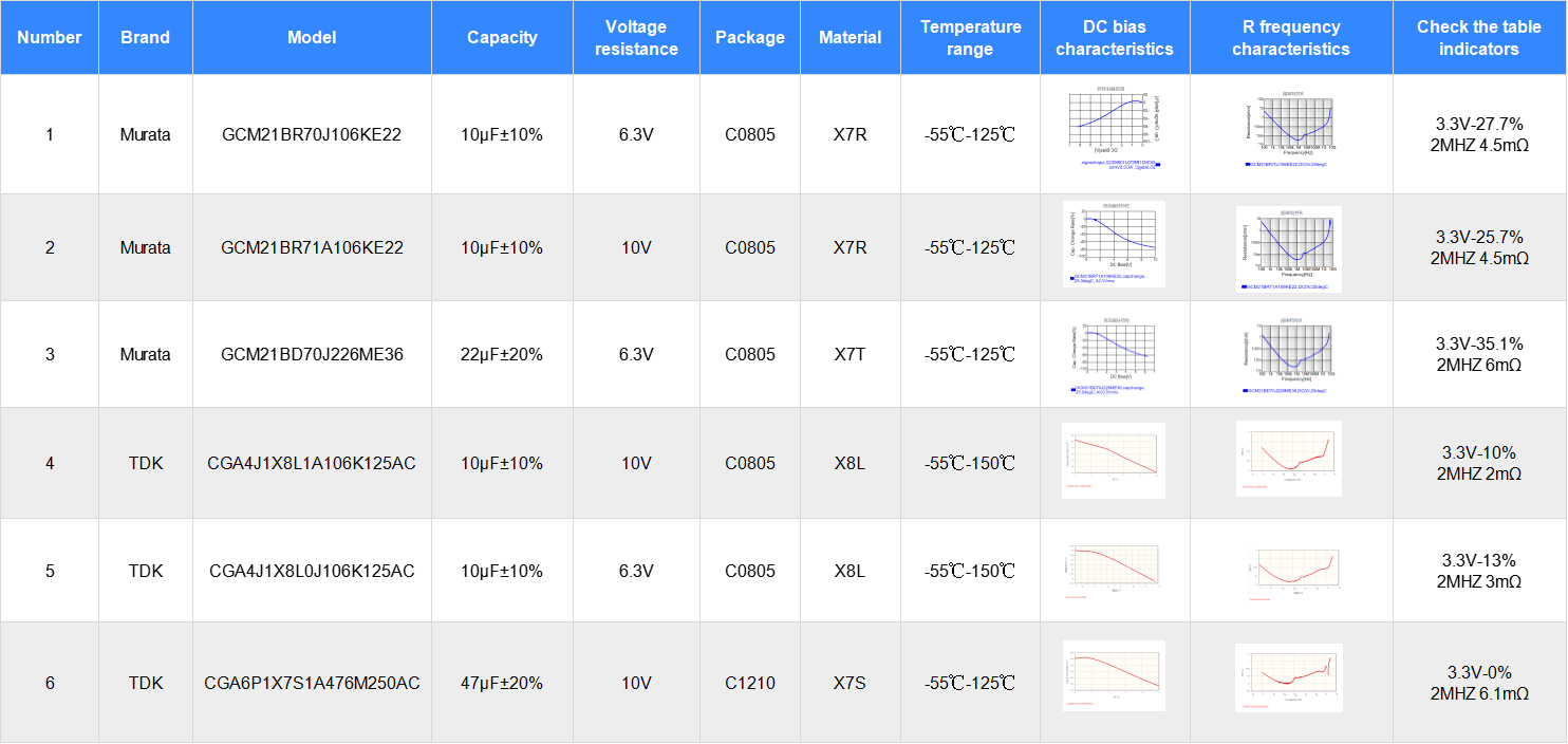
Table 15: Recommended Selection of Output Filter Capacitor Models for Switching Power Supply
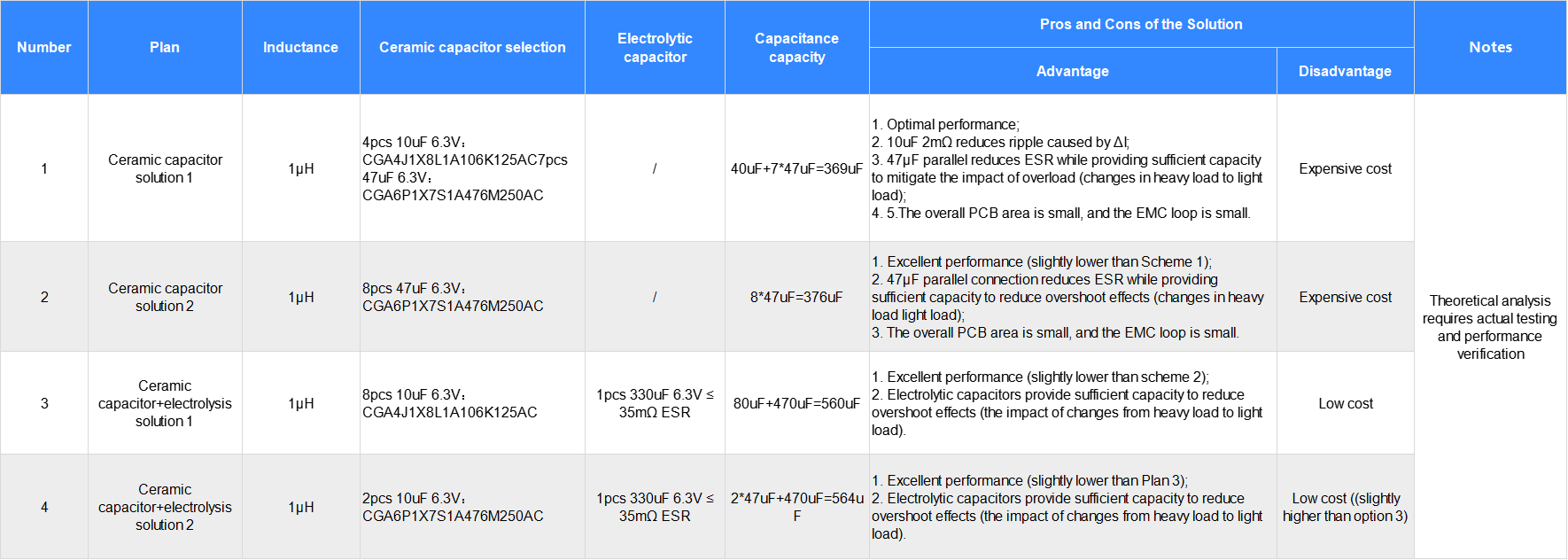
Table 16: Design of Output Filter Capacitors for Switching Power Supplies
4.3 Calculation of Input Capacitor for LM25149 power supplier
4.3.1 Input Capacitance Calculations
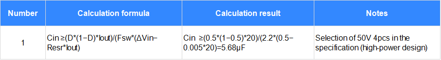
Table 17: Calculation of Input Filter Capacitor for Switching Power Supply
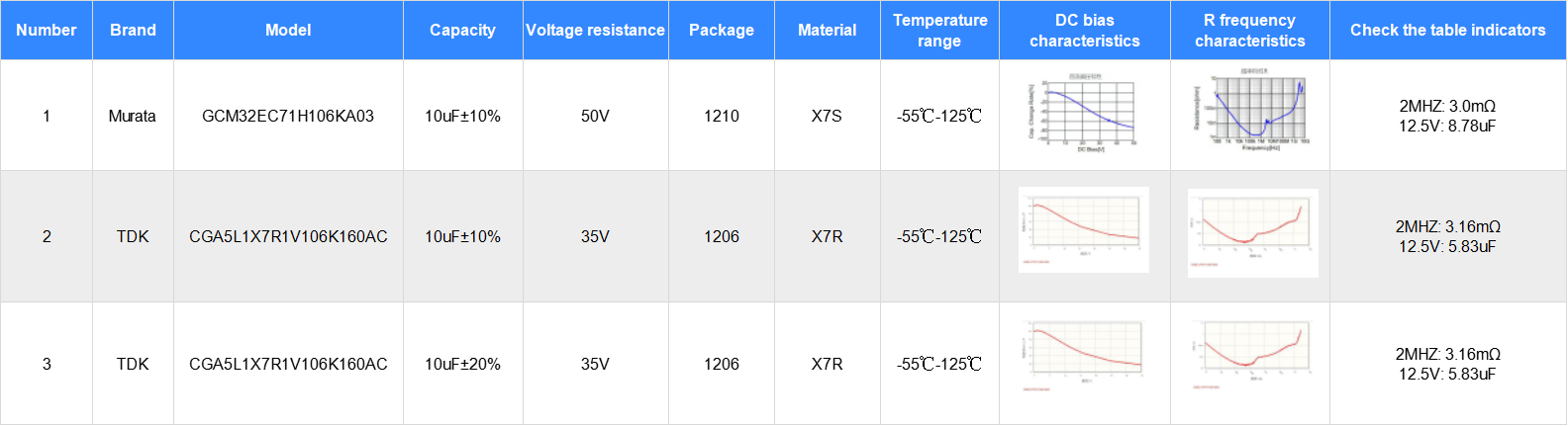
Table 18: Selection of Output Filters for Switching Power Supplies
4.4 LM25149 MOSFET Selection Calculation
4.4.1 MOSFET Calculation
The LM25149 datasheet does not include many calculations and selection calculations. QG calculations and selections are based on empirical estimations and reverse deductions. The calculation results indicate a value of 4.5-5.0V Vgs and ≤22nC. The calculation process is shown in the table below. The Miller platform is selected as 2-3V (close to 3V is also acceptable), and Rdson is selected as ≤8mΩ.
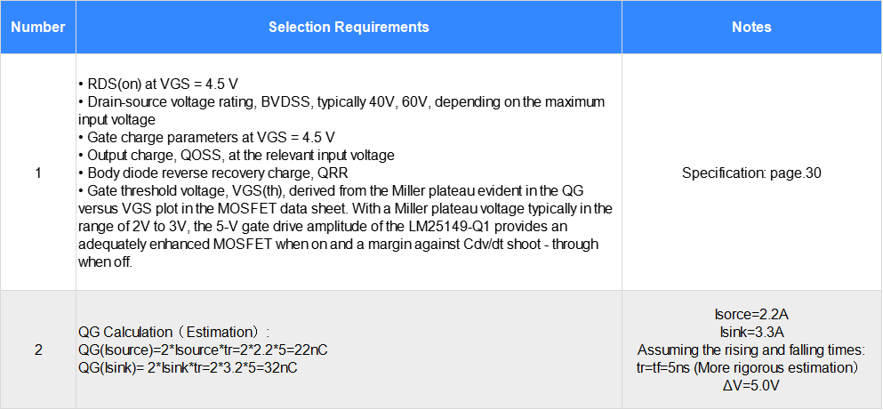
Table 19: MOSFET Selection and Calculations
4.5 MOSFET Selection Recommendations
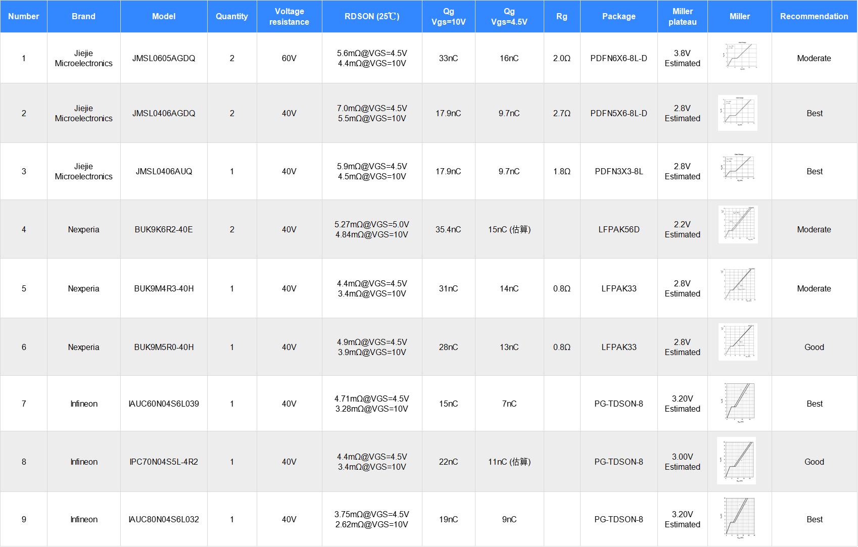
Table 20: MOSFET Selection Models
4.6 LM25149 FB and Compensation Calculations
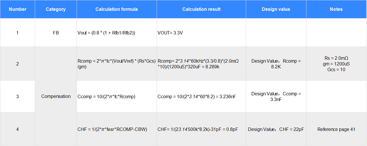
Table 21: FB and Compensation Calculations
4.7 LM25149 EMC Design Calculation
Without going into too much analysis, refer to the specifications.
5- Design Summary
5.1 Summary of LM25149 BUCK Power Supply Design and Selection
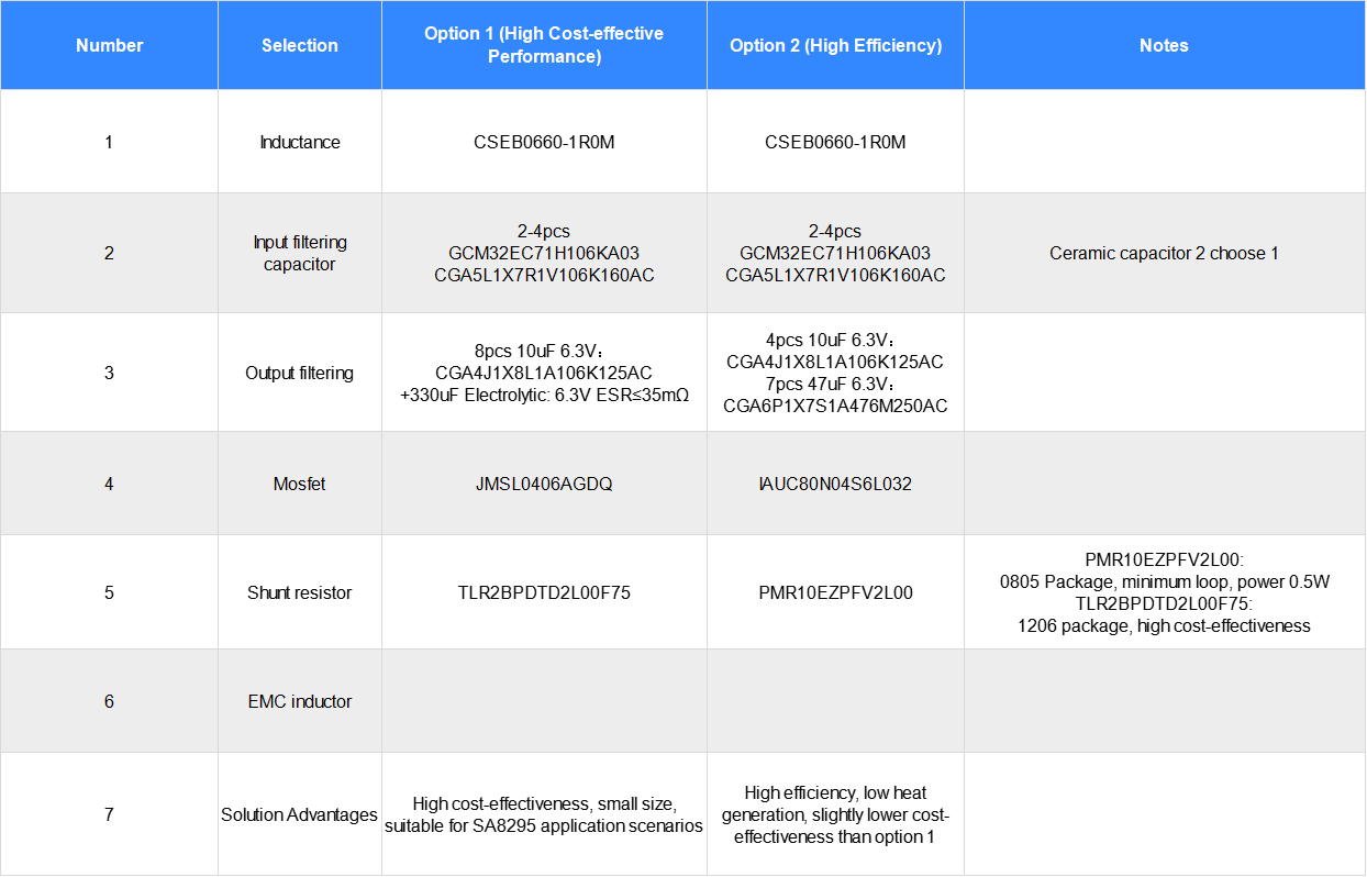
Table 22: Design and Selection
5.2 Summary of the Solution
The performance and efficiency of synchronous switching power supplies are affected by many factors. Performance and specifications need to take into account practical factors. This chapter is used for theoretical calculations to provide theoretical guidance for practical design. The performance and specifications of the design are closely related to component performance, usage conditions, layout, etc., and require rigorous testing and verification.
Synchronous buck power supply design for Qualcomm domain controllers is a challenging area of controller design, requiring a balance between performance, size, and cost. CODACA focuses on independent R&D and design of power inductors and common mode chokes. The CSEB0660-1R0M is suitable for Qualcomm platform development and applications, offering high cost-effectiveness, strong resistance to saturation current, low heat generation, and industry-leading power-to-volume ratio. CODACA is dedicated to technological R&D and innovation, developing excellent products for the inductor industry and contributing to the development and application of electronic products.