
 EN
EN
Quick Links

With the rapid development of the new energy vehicle industry, the On-Board Charger (OBC) serves as the core connection component between the power grid and the power battery, making its electromagnetic compatibility (EMC) design increasingly vital. High-speed switching of power devices in switching mode power supplies generates high-frequency EMI interference, which includes both common-mode and differential-mode conducted noise transmitted along power lines, as well as spatial radiated interference. On-board chargers must feature a robust EMC filter design to adapt to the complex automotive electromagnetic environment, ensure their own stable operation, and prevent interference with other electronic equipment in the vehicle. Among these, the common-mode choke and theπ-type filter circuit are the core components of EMC filtering, and inductor selection directly determines filtering performance, overall system volume, and thermal reliability.
1- EMI Noise Sources and Filter Architecture
When an OBC is operating, its front-end PFC circuit's high-frequency switching tubes (IGBTs or SiC MOSFETs) and the rear-end DC-DC converter's resonant circuits generate a significant amount of harmonic components. Conducted EMI noise is classified into two types: differential-mode noise and common-mode noise. Differential-mode interference exists between the two power input lines (such as between the L line and N line) with opposite current directions, primarily caused by current ripples generated in the power loop due to high-speed turn-on and turn-off of the switching tubes; common-mode interference exists between the power lines and the ground line (PE) with the same current direction, primarily caused by high-voltage transient nodes during switching actions coupling to ground through parasitic capacitance, as well as external electromagnetic field coupling.
The input end of an OBC is typically configured with aπ-type EMI filter circuit, using a combination of inductors and capacitors to suppress electromagnetic interference across different frequency bands. The general architecture of the filtering network consists of an X capacitor (differential-mode filtering), a common-mode choke, a Y capacitor (common-mode filtering), and a differential-mode inductor arranged sequentially from the grid side, forming a two-stage or multi-stage filtering structure. The front stage mainly deals with conducted interference and harmonics from the grid side, while the rear stage is responsible for further attenuating high-frequency noise generated by switching actions。
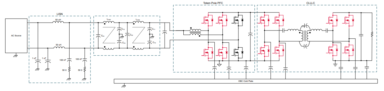
Figure 1. OBC Schematic Diagram
2- Working Principle and Core Material Selection for Common Mode Chokes
2.1 Working Principle
A common-mode choke is wound on a closed magnetic core with coils having opposite directions and the same number of turns to achieve high-impedance suppression of common-mode noise. When common-mode current flows through, the magnetic flux direction of the windings is identical and superimposes, causing the common-mode choke to present a high impedance, thereby effectively attenuating common-mode signals. When differential-mode current (such as normal operating current) flows through the two windings, the magnetic flux directions generated in the core are opposite and cancel each other out, allowing differential-mode signals to pass through with almost no attenuation.
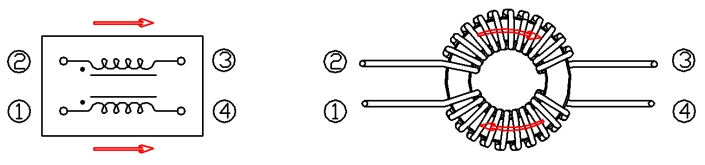
Figure 2. Magnetic fields superimpose when common-mode current flows through
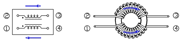
Figure 3. Magnetic fields cancel each other out when differential-mode current flows through
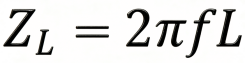
According to the impedance formula of a common-mode choke:
And the inductance formula:
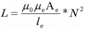
The effective magnetic permeabilityμeof the core directly determines the inductance obtained under a given size and number of turns. The higher the permeability, the higher the impedance under the same size, resulting in a stronger filtering effect.
2.2 Magnetic Core Material Selection
Commonly used core materials for common-mode chokes include manganese-zinc ferrite, nickel-zinc ferrite, amorphous alloys, and nanocrystalline alloys.The differences in their characteristics determine their respective application boundaries:
◾ Ferrite: A Cost-Effective Choice for Medium to High-Frequency Applications
Ferrite (such as Mn-Zn, Ni-Zn) has become the preferred material for high-frequency common-mode chokes due to its high resistivity and low eddy current loss.Mn-Zn ferrite performs excellently in the 100kHz-1MHz frequency band, but its Curie temperature is relatively low (about 120℃),causing permeability to drop sharply at high temperatures; Ni-Zn ferrite is suitable for frequency bands above.Although its initial permeability is low(μ<1000),its high-frequency stability is superior.
◾ Amorphous and Nanocrystalline Alloys: The Ultimate Solution for High-Frequency, Low-Loss Applications
Amorphous alloys (such as iron-based and cobalt-based) form a disordered atomic structure through a rapid quenching process, exhibiting extremely high saturation magnetic flux density(Bs1.2T) and extremely low high-frequency loss. Nanocrystalline alloys further form a nanocrystalline structure through heat treatment, reducing loss by more than 50% compared to ferrite in the 100kHz-500kHz frequency band, and significantly improving temperature stability. They are suitable for scenarios with strict efficiency requirements, such as electric vehicle charging modules.
2.3 Key Selection Points for Common Mode Chokes
(1)Inductance: Select the appropriate inductance based on the operating frequency and interference characteristics of the on-board charger.Generally, a higher inductance provides better low-frequency suppression but increases the insertion loss of the circuit.Typically, the inductance of common-mode chokes ranges between a few hundred microhenries(μH)and a few millihenries(mH).
(2) Rated Current: The rated current of the common-mode choke should be greater than the maximum operating current of the on-board charger to prevent efficiency degradation of the entire system caused by inductor heating, while also ensuring excellent stability of the inductor under the rated current.
(3) Frequency Characteristics: Choose a common-mode choke with good high-frequency suppression characteristics to meet the wideband interference suppression requirements of the on-board charger. Check the impedance vs. frequency curve of the common-mode choke to ensure sufficient impedance within the target frequency range.
For high-power OBC application scenarios, automotive-grade common-mode chokes are primarily driven by customized requirements. The R&D team of CODACA Electronics has extensive experience in the customized development of common-mode chokes and can rapidly provide matching product solutions based on customer characteristic requirements.
3- Principle of π-type Filter Circuit and Key Selection Points for Differential Mode Inductors
A π filter circuit consists of two capacitors and a differential-mode inductor, shaped like the letter π. It utilizes the bypass effect of capacitors and the filtering effect of inductors to effectively suppress differential-mode interference. In on-board chargers,π-type filter circuits can further reduce interference signals on power lines and improve EMC performance. The typical switching frequency of an OBC ranges from 40kHz~150kHz, and conducted emission testing starts from 150kHz. Therefore, differential-mode filtering primarily targets differential-mode noise in the 150kHz~1MHz frequency band.
The cutoff frequency formula for aπ-type filter is:
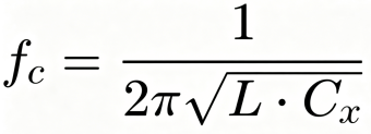
Where Cx is the equivalent capacitance of the two-stage X capacitors in theπ-type filter. (In actual designs, two stages of X capacitors with the same capacitance are frequently used, so the combined equivalent filtering capacitance is usually conservatively estimated based on a single-stage X capacitor value). The design must ensure that the cutoff frequency is significantly lower than the fundamental switching frequency, typically taken as 1/5 to 1/10 of the switching frequency, to ensure the target interference frequency band falls within the stopband of the filter.
3.1 Working Principle of Differential Mode Inductors
A differential-mode inductor mainly consists of a single winding connected in series within the power input line. By utilizing the impedance characteristics of the inductor against high-frequency currents, it forms a high-impedance path for differential-mode interference between the L line and N line, achieving noise attenuation. When selecting an inductor, shielded inductors are preferred to reduce external radiation and external interference.
(1) Inductance: Inductance is the most fundamental parameter of a differential-mode inductor, determining its ability to suppress noise at specific frequencies. The target filtering frequency band needs to be considered during selection; a larger inductance generally provides more significant suppression effects on low-frequency noise.
(2) Rated Current: This refers to the maximum current under which the inductor can operate safely long-term under specified temperature rise conditions. Selection must ensure that the maximum operating current is less than the rated current, leaving an ample margin (typically> 30%).
(3) DC Resistance (DCR): DC resistance refers to the internal resistance of the inductor winding coil under DC conditions. The lower the DCR, the smaller the power consumption generated when DC passes through, thereby improving overall efficiency.
Since OBC is belong to automotive applications, the inductors must satisfy the AEC-Q200 automotive electronics reliability standards. Test items include: electrical performance testing, mechanical shock testing, vibration testing, terminal strength testing, solderability testing, biased humidity testing, temperature cycling testing, high-temperature storage testing, etc. CODACA can provide various types of standard automotive-grade power products.
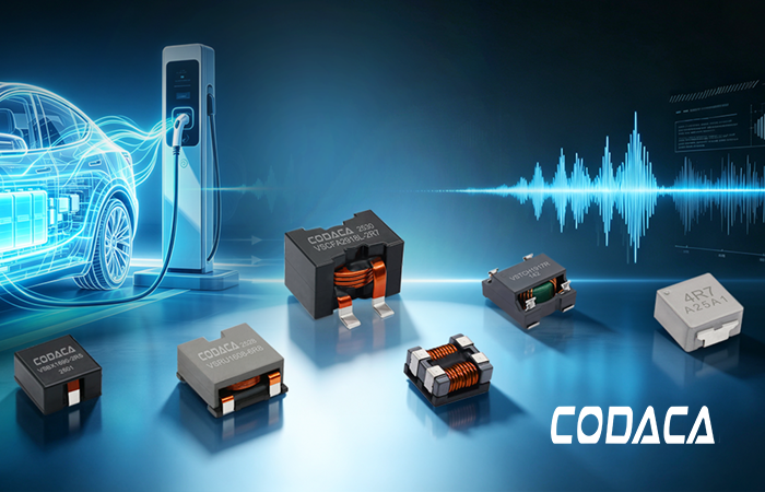
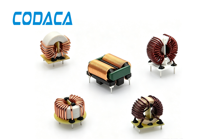
Below is a showcase of some automotive-grade inductors. For details, please visit the official website of CODACA Electronics at https://www.codaca.com.cn/, or contact CODACA sales personnel. Enquiries are highly welcome.
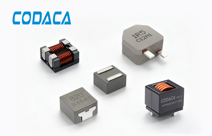
Figure Caption: Figure 4. CODACA Automotive-Grade Inductor